
By Chad Hanson, AMP Tech Team.
Many flux sites do not have access to line power, and run on solar power. This post shares my recent experience of building a simple solar system, and the design considerations that went into it. We hope this will help others as they design and maintain their own systems. Please use the Comments at the bottom of the blog to share solutions you’re using with other members of the flux community.
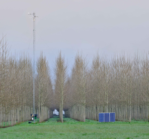
New solar powered hybrid poplar flux site, Lane County, Oregon
Determining the load
The first step is to determine what the electrical loads will be at the site. Research sites are easier to quantify than off grid houses because we tend to have constant 24 hour loads. As a point of reference, a typical open path eddy covariance system like the one at the poplar site in this example, with basic met sensors and cellular communication modem will draw between 2-3 amps continuous at 12 volts. This equals 24-36 watts (remember Power (Watts) = Current (amps) x Voltage (volts)). Watts is what we want, so we can determine the watt hours we need to produce and store. In our example we’ll use 36 watts for 24 hours or 864 watt/hours per day, and 25.92 KwH per month.
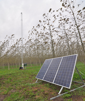
Poplar site solar array
Array sizing
Next we need to determine how much solar energy is typically available at the site location. Because we want to run our site all year, we need to focus on the darkest month. This is typically December due to day length, but some areas may have seasonal weather patterns that reduce the available radiation more in other months. The National Renewable Energy website offers excellent data at:
http://www.nrel.gov/gis/solar.html
By looking at the map for December at our site, we see that we get ~2 KwH per m2 per day. This unit is also referred to as sun hours in the solar energy world and is equivalent to hours of full noontime sun per day.
Now that we have the energy needed and available, we can calculate the size of the solar array required to run our site through the winter.
We will combine the needed power harvest per day with the energy per square meter per day with an efficiency coefficient to arrive at a theoretical minimum solar panel array size. There are many approaches to estimate the loss in efficiency from tilt angles, charge controllers and wiring losses. The easiest way to do this is to use one of the many off-grid calculators available, such as:
http://www.wholesalesolar.com/solar-information/start-here/offgrid-calculator
For our example we will use a modern maximum power point tracking (MPPT) controller and multiply our 864 wH/day by an efficiency factor of 1.5 to arrive at a needed daily harvest of 1296 watt hours. Dividing this value by the 2 hours of full sun equivalent per day at our site in December, we find that we will need a minimum of 648 watts of solar panels to meet our energy needs.
As of this post (March 2015) the cost of solar panels is ~ $1.00 per watt or less for 305 watt, 35 volt panels. For the poplar site I chose to use three 305 watt panels wired in parallel to give a little bit of overhead for future power needs and to help us generate more power on overcast days. In larger systems it is advisable to connect the panels in an array through a dedicated combiner box with circuit breakers for each panel to allow easy maintenance and expansion of the system. For this small system I combined the panels in parallel using hardwired combiner blocks and then ran array power to the main enclosure.
Using 35 volt panels offers several advantages over older 17 volt models. First, the higher voltage between the array and the charge controller minimizes voltage drop due to resistance in the wires. This allows moving the array further from the battery bank or improved overall efficiency. Second, modern charge controllers use maximum power point tracking (MPPT), and can take advantage of elevated panel voltage to boost the charging current to the batteries offering significantly better charging efficiency.
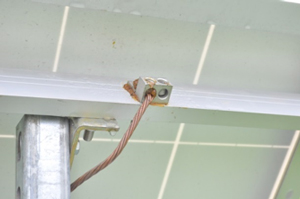
Make sure to protect the junctions where the panels are combined and to ground the metal frame of the array. Also make sure to keep high current lines in conduit.
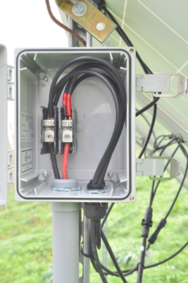
Combining panels
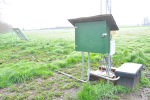
Base of tower with charge controller enclosure and battery box
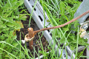
Solar panel ground
Another grounding
Battery bank size and voltage
The primary consideration for battery sizing is the days of autonomy needed at the site. This can be really hard to know in advance and usually cost is limiting here. A week or two of cloudy or foggy weather is not uncommon at some point in the year at most northern locations but a battery bank big enough to last that long could literally break the bank. I have had good performance from the Trojan L16RE-B series of batteries. They are rated at 2200 Watt hours each, and can usually be found from between $285-$345 and have proven to be very durable (tolerant of over discharge…). These are flooded lead acid batteries so you will need to check the water level every 2 months or so but I have found the newer versions loose water very slowly. This inconvenience is made up for by getting much larger capacities per dollar compared to sealed batteries.
Most of the sensors associated with a micro met research site run on 12 volts DC. This makes it convenient to run a 12 volt battery bank. On tall towers this can cause loss in efficiency from voltage drop and correspondingly larger conductors are needed to keep this in check.
At the poplar site I ended up with a 12 volt bank made up of 4, 6 volt cells wired in series and parallel, for a bank capacity of 8880 watt hours. In theory this would run the site for 10 days from a full charge. In practice that would mean completely discharging the batteries and damaging them. We only want to discharge them to 50% if we hope to get a long life span out of them so we end up with 5 days of autonomy before the load controller will turn off power. A bank will last ~5 years in when discharge is kept to 50% or less.
Ideally batteries should be placed in an insulated battery box especially in very cold or very hot climates to help prolong their life.
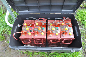
A 12 volt bank made up of series and parallel wired 6 volt batteries. Note red anticorrosion treatment on terminals.
Charge, load control, and power distribution
It is important to keep your charge controller and power panel in a separate enclosure from the batteries to prevent corrosive fumes from damaging the electronics. I bring my combined solar array power through a circuit breaker then into the charge controller. From the charge controller there is an additional breaker that feeds the batteries. Battery power then comes back to the panel and powers the site loads through a third circuit breaker and a load control relay managed by our data logger. The data logger has a direct connection to the battery bank separate from sensor power so it can turn the loads back on when the bank recharges. I set the logger to turn off the loads when voltage drops below 11.8 volts and back on when it exceeds 12.2 volts.
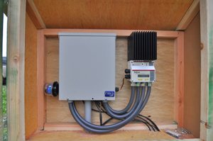
An enclosure for the charge controller and power panel, separated from the batteries.
You need to use appropriate DC rated breakers and pay attention to the polarity when arranging their placement in the circuit. Commonly available AC circuit breakers will not work. To determine the current rating for each breaker a typical approach is to use 1.2 to 1.5 times the expected load.
My main power enclosure is a Midnight Solar MNPV12 combiner box. This is normally used to combine solar panels in larger systems. It is convenient and cost effective as an enclosure for small systems because it comes with buss bars for feeding the various circuits and grounding and also has a DIN rail and cover for the circuit breakers. I also added a current sensing shunt that lets me monitor the power use of the site on our main data logger. If you have a choice always use the biggest enclosure you can. It will make wiring much easier. Last but not least there is a lightning arrestor mounted to the side of the panel and wired positive, negative and ground that functions to divert voltage spikes to ground and protects the electronics in case of a lightning strike.
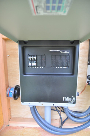
Load control – circuit breaker.
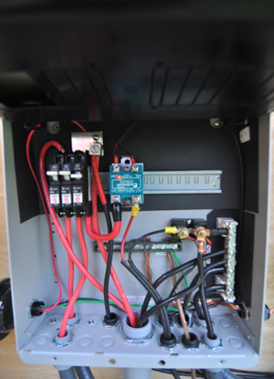
Inside the circuit breaker panel: power distribution.
How much did it cost?
This 915 watt solar system with 5 days of autonomy cost roughly $3500. It should be noted that we had the good fortune of a ground based southern exposure which is uncommon for a forest research site. In the past we have had to build a second tower to locate panels above the canopy. Also, if you build it they will come, or put another way, more sensors and measurements are always wanted at research sites so it is good whenever possible to oversize your power system or at least build it with future expansion in mind.
Parts used
- Trina 305 watt panels
- Site built Unistrut rack
- Iron ridge mounting rails and panel clamps
- 4awg stranded wire for array to main panel , and charge controller to battery runs (these are high current)
- Morningstar 45 amp MPPT charge controller with digital display (networkable for remote monitoring)
- Trojan L16RE-B 6 volt batteries
- Continental SVDD-1V20 solid state relay (20amp max) with Crydom HS501DR DIN mount
- Midnight solar MNPV12 combiner box
- Midnight solar surge protector MNSPD300-DC
- Midnight solar breakers
Share your experiences or ask questions in the comments section below!
Post and photos by Chad Hanson, chad.hanson@oregonstate.edu.

Chad Hanson
On behalf of Matt Meiresonne, Engios http://www.engios.com/ –
I am from Engios.com, our content team recently published an interesting post on Solar Panel Output Energizers That Boost Efficiency so I thought you might be interested in having a look.
Here is the link – http://www.engios.com/solar-panel-output-efficiency/
Love to have your feedback!